Voltage
Current
Sensor Element
Hysteresis
Voltage Rating | 125–250 Vac |
Current Rating | 16 A (AC) / 14 A (DC) |
Contact Type | SPST (NO / NC) |
Control Type | Operating control, Type 1 |
Dielectric Strength | 1800 Vac · 1 sec |
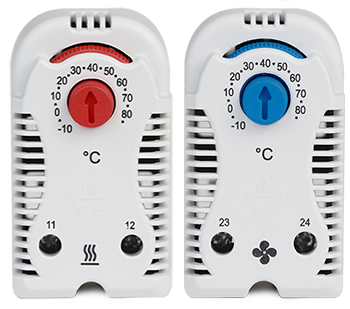
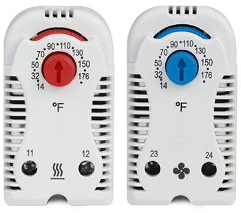
Temperature Range | -10 to +80 °C (+14 to 176 °F) |
Hysteresis | ±5°C |
Sensing Element | Bimetal |
Housing Materia | Flame retardant housing, UL 94-V0 |
Colour | RAL 7035, Light Grey |
Length | 47 mm / 1.85″ |
Width | 34 mm / 1.34″ |
Height | 60 mm / 2.36″ |
Weight | 50 g / 0.11 lb |
Mounting | Rail 35 mm / Rail 32 mm / Rail 15 mm |
Terminals | 2-Pole for wires section of 12 AWG |
Standards | UL 60730-1 / UL 60730-2-9 / UL 60730-2-13 CAN/CSA-E60730-1:15 / CAN/CSA-E60730-2-9:15 |
Environmental | Indoor |
Specifications and key features for quick reference.
Operation, safety notes, and troubleshooting.
Outline drawings with dimensional data.
Precision thermal control for automation OEMs and panel builders, protecting critical electronics from heat and condensation.
High-capacity, low-noise cooling to maintain tight temperature tolerances in server racks and AI nodes.
Weatherproof thermal solutions to ensure performance and safety in both indoor and outdoor charger installations.
Rugged, IP and NEMA rated systems for avionics, radar, and control cabinets in mission-critical environments.
Reliable cooling and humidity control for telecom shelters, network hubs, and remote facilities.
FDA compliant solutions with hygienic design to safeguard against moisture and contamination in certified environments.
Thermal protection for inverters and junction boxes exposed to harsh sunlight and temperature swings.
Corrosion-resistant heaters, fans, and hygrostats suitable for humid and chemically aggressive conditions.
Durable cooling for cabinets at intersections, highways, and remote signaling, resistant to weather extremes.
Contact type (NO/NC), setpoint, differential, voltage/current rating, mounting (DIN/plate), sensor type (integral/remote), and required approvals.
See the Documents tab on each product page for datasheets, wiring diagrams, UL/CSA files, RoHS/REACH and installation guides.
Use two thermostats for independent thresholds (e.g., NC at 10 °C for heater; NO at 35 °C for fan). A dual-thermostat module is also common.
Use NC to protect against over-heating of a heater (opens as temp rises). Use NO to start cooling fans when cabinet temperature rises above your target.
Common starting points: Heater NC ~10–15 °C (anti-condensation) and Fan NO ~30–35 °C (electronics comfort). Adjust for climate, load, and component specs.
5–10 K suits most enclosures—small enough to hold temperature steady, large enough to avoid short-cycling.
If condensation risk exists, pair a hygrostat (60–65% RH) in series with an NC thermostat near your minimum temp so the heater runs only when humid and cool.
Size for locked-rotor/inrush (fans can be 3–6× running current; PTC heaters have a brief surge). If in doubt, switch a control relay instead of the load directly.
Yes, if the total inrush and running current are within contact ratings. Otherwise, use a contactor/relay.
Mid-height, away from direct airflow and heat sources, close to the warmest representative spot of the components you’re protecting.
Line → COM; NO → fan line; neutral direct to fan. The contact closes on temperature rise to power the fan.
Line → COM; NC → heater line; neutral direct to heater. The contact opens on temperature rise to stop heating.
For anti-condensation: Hygrostat (60–65% RH) in series with NC thermostat set near your minimum temperature → heater runs only when both conditions are met.
Yes—cabinet design, airflow, and thermostat placement influence readings. Avoid cold walls or direct fan streams.
Mechanical thermostats are generally robust. For high vibration, secure DIN clip, use strain-relief, and consider electronic types for precision.
Use NC thermostat near 10–15 °C plus a hygrostat at 60–65% RH controlling a PTC or resistive heater; keep intake fans off while RH is high.
Yes—use two NO thermostats at different setpoints (e.g., 30 °C for Fan #1, 38 °C for Fan #2) or one thermostat driving a two-stage controller.
Use the thermostat to enable the controller (run/stop) while the controller handles speed modulation from a temperature probe.
Check NO vs NC wiring, verify supply voltage, confirm setpoint, and ensure the thermostat isn’t in the direct cold airstream from an intake.
Verify you used NC contact, confirm setpoint isn’t too high, ensure hygrostat series wiring (if used) is correct, and check for welded contacts (sign of overload).
Load may be inductive or over current. Add snubber/MOV, switch a relay, or upsize the thermostat/relay.